The image above is for illustration purpose only. The actual module may vary from the one presented here.
Module M-AV-AMP-s is a component of the Ampio system. Required voltage to power the module is 11 — 16V DC. The module is controlled via CAN bus.
Adding the module to the Ampio installation makes it possible to play music automatically when someone enters the house, or lower the volume after a certain hour. It provides a lot of functionalities that can be customised per user.
The module has a built-in 2 x 15W amplifier, thanks to which we can connect speakers directly to it. The amplifier has a thermal safety feature - if the temperature exceeds a safe limit, the volume will be automatically reduced to avoid damaging the device.
Two line audio inputs allow for connecting various sound sources, e.g.: MP3 player, shelf stereo, Bluetooth transmitter, CD player, etc.
Changing sound sources is possible via the mobile app, or on the touch panels, if they are properly configured. With a built-in FM radio receiver, you can programme 16 different radio stations in the module.
The line out audio output makes it possible to connect an external amplifier in order to, e.g. use more powerful speakers, or use an existing audio system.
RDS information such as, e.g. a radio station name can be shown on the touch panels’ displays.
The module can be controlled either via the Ampio touch panels, or the mobile app available on iOS and Android devices.
The module is equipped with a USB connector that can supply power to an external device with a current consumption not exceeding 500mA. The power output can be turned on and off from the building automation system.
The module is designed for mounting on a 35mm DIN rail. The module’s width is 105mm, 6 spaces/modules in DB. In order to start the module, it must be connected to the CAN bus. The bus of the Ampio system consists of four wires - two for power and two for communication between the modules.
If the built-in audio amplifier is to be used, in addition to the standard connection of the M-AV-AMP-s module to the Ampio system’s CAN bus, it is also required to connect an additional power line with a voltage of 11 — 16V DC and current efficiency of 5A. It is used to power the built-in audio amplifier.
Connecting an FM antenna via SMA connector is a prerequisite to the proper working of the radio receiver.
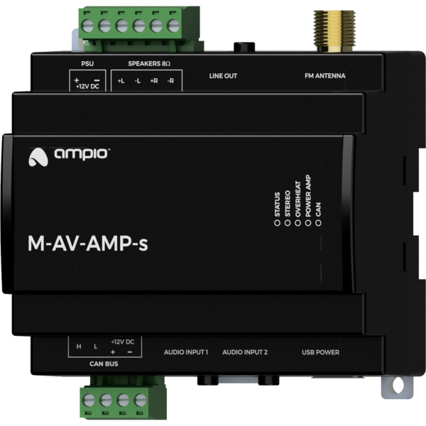
The module has two jack 3,5mm connectors that allow for connection up to two external stereo signal sources, and one connector serving as a stereo line output that allows the audio signal to be passed to an external amplifier. In addition, it has a USB connector that allows to power an external device.
On the front of the module there are signalling LED indicators. The green LED with the label CAN indicates the status of communication on the CAN bus:
Apart from the communication bus status LED, there are 4 red LEDs on the front of the device:
The module is programmed with the use of the Ampio Designer software. It allows you to modify the parameters of the module and define its behaviour in response to signals directly available to the module as well as general information coming from all devices present in the home automation bus.
Dimensions expressed in millimeters.
 Click to enlarge and open in a new tab.
